


-
-
gbFurther countries
 Great Britain (EN)


Channel side wall
Al alloy

Standard lengths for channel side wall 2000 mm
Standard lengths for clamping profile 130 mm
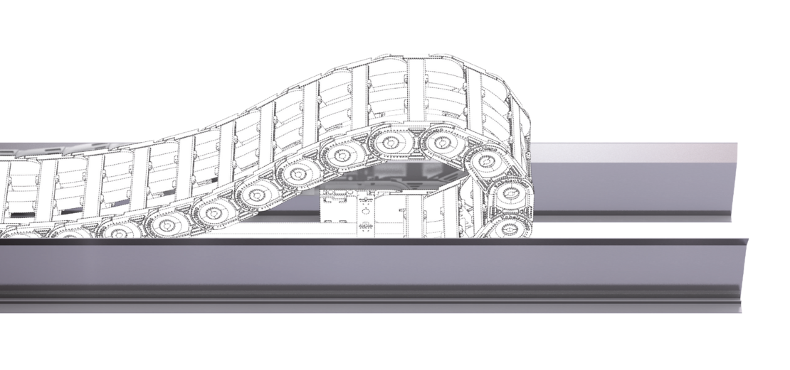
For one-sided arrangement of the cable carrier, the cable carrier slides behind the fixed point on a continuous slide support with run-off bevels.
Channel profile with and without supports incl. run-on bevels.
Dirt and water can drop through without restrictions.
Channel profile with and without supports incl. run-on bevels.
Dirt and water can drop through without restrictions.
For opposite arrangement, a slide support is also attached for bridging between the fixed point connections.
Channel profile with and without supports incl. run-on bevels.
Dirt and water can drop through without restrictions.
Channel profile with and without supports incl. run-on bevels.
Dirt and water can drop through without restrictions.


The cable carrier outer width without attachments Bk is taken into account for calculating the inner width of guide channel b1 and the overall width BKA.
| Type | Design | h1 [mm] | h2 [mm] | hKA [mm] | b1 [mm] | b2 [mm] | BKA [mm] | s1 [mm] | s2 [mm] | D [mm] | |
|---|---|---|---|---|---|---|---|---|---|---|---|
| 0130/0132 | |||||||||||
| – | A | 18 | 1.5 | 38 | Bk + 3 | Bk + 16 | BK + 26 | 1.5 | – | 6 | |
| 0180/0182 | |||||||||||
| – | A | 18 | 1.5 | 38 | Bk + 3 | Bk + 16 | BK + 26 | 1.5 | – | 6 | |
| 0202 | |||||||||||
| – | A | 18 | 1.5 | 38 | Bk + 3 | Bk + 16 | BK + 26 | 1.5 | – | 6 | |
The cable carrier outer width without attachments Bk is taken into account for calculating the inner width of guide channel b1 and the overall width BKA.
| Type | Design | h1 [mm] | h2 [mm] | hKA [mm] | b1 [mm] | b2 [mm] | BKA [mm] | s1 [mm] | s2 [mm] | D [mm] | |
|---|---|---|---|---|---|---|---|---|---|---|---|
| QT0320 | |||||||||||
| – | B | 27.5 | 1.5 | 55 | Bk + 3 | Bk + 29 | BK + 42 | 1.5 | – | 7 | |
The cable carrier outer width without attachments Bk is taken into account for calculating the inner width of guide channel b1 and the overall width BKA.
| Type | Design | h1 [mm] | h2 [mm] | hKA [mm] | b1 [mm] | b2 [mm] | BKA [mm] | s1 [mm] | s2 [mm] | D [mm] | |
|---|---|---|---|---|---|---|---|---|---|---|---|
| UA1320 | |||||||||||
| – | B | 27.5 | 1.5 | 55 | Bk + 3 | Bk + 29 | BK + 42 | 1.5 | – | 7 | |
The cable carrier outer width without attachments Bk is taken into account for calculating the inner width of guide channel b1 and the overall width BKA.
| Type | Design | h1 [mm] | h2 [mm] | hKA [mm] | b1 [mm] | b2 [mm] | BKA [mm] | s1 [mm] | s2 [mm] | D [mm] | |
|---|---|---|---|---|---|---|---|---|---|---|---|
| ET0180 | |||||||||||
| – | A | 18 | 1.5 | 38 | Bk + 3 | Bk + 16 | BK + 26 | 1.5 | – | 6 | |
| ET0320.030 | |||||||||||
| – | B | 27.5 | 1.5 | 55 | Bk + 3 | Bk + 29 | BK + 42 | 1.5 | – | 7 | |
The cable carrier outer width without attachments Bk is taken into account for calculating the inner width of guide channel b1 and the overall width BKA.
| Type | Design | h1 [mm] | h2 [mm] | hKA [mm] | b1 [mm] | b2 [mm] | BKA [mm] | s1 [mm] | s2 [mm] | D [mm] | |
|---|---|---|---|---|---|---|---|---|---|---|---|
| M0320 | |||||||||||
| – | B | 27.5 | 1.5 | 55 | Bk + 3 | Bk + 29 | BK + 42 | 1.5 | – | 7 | |
The cable carrier outer width without attachments Bk is taken into account for calculating the inner width of guide channel b1 and the overall width BKA.
| Type | Design | h1 [mm] | h2 [mm] | hKA [mm] | b1 [mm] | b2 [mm] | BKA [mm] | s1 [mm] | s2 [mm] | D [mm] | |
|---|---|---|---|---|---|---|---|---|---|---|---|
| TKA30 | |||||||||||
| – | B | 27.5 | 1.5 | 55 | Bk + 3 | Bk + 29 | BK + 42 | 1.5 | – | 7 | |
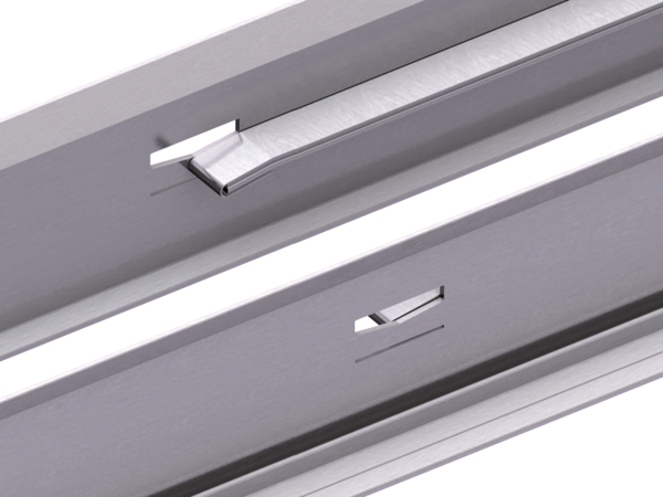
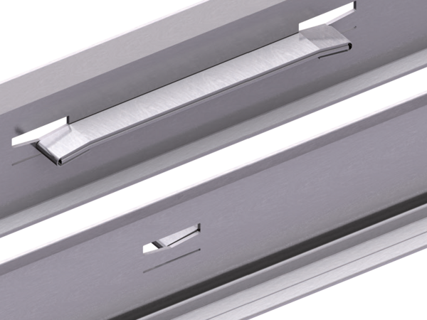
Fixing holes are drilled for this purpose. A marking groove facilitates alignment and drilling.


To order the Aluminium channel , please provide the following information:
Reliable, robust with high availability. Your benefit from many years of experience combined with ongoing optimization, proven in tests and praxis. TRAXLINE® cables stand for competent system-supply with worldwide on-site service.
to TRAXLINE®From pre-assembled cables to complex, ready-to-connect systems, from lot size 1 to series – worldwide thousands of KABELSCHLEPP systems are reliably in use. The benefits of TOTALTRAX® systems are obvious: just one person of contact, one order number, delivery just-in-time to your production facility, shortest downtimes thanks to plug&play installation.
to TOTALTRAX®Reliable unrolling and optimum gliding for long travel lengths
to Support traysFor optimum placement with dynamic use of cables
to Strain relief devicesConfiguration guidelines:
The latest TSUBAKI KABELSCHLEPP information material:
Our product filter supports you in finding the right cable carrier. Simply select your desired parameters and you will quickly get an overview of all suitable type series.
 Inner height
 Outer height
 Inner width
 Outer width
 Inner width (Bi) in x mm increments
 Pitch
Pitch
 Bending radius
 Long travel length
 Travel length unsupported
 Travel length gliding
 High additional load
 High travel acceleration
 High travel velocity
 Stay arrangement on every 2nd chain link
 Stay arrangement on every chain link
 Cannot be opened
 Opens outward
 Opens outward
 Opens inward
 Opens inward
 Opens inward/outward
 Covered cable carrier
 Sliding dividers
 Fixable dividers
 Fixable dividers in x mm grid
 Height separation possible
 Height separation in 1 mm increments
 Hole stay available
 Guide channel required
 Strain relief
 Clean room suitable
 Quiet running/low noise
 Sold by the meter
 Low weight
 Roller chain
 ESD material
 Ex-protection-material
 Heat-resistant
 Cold-resistant
 Resistant to hot chips
 Flame-resistant V0 (UL94)
 Flame-resistant V2 (UL94)


