


hore 


The maximum cable diameter strongly depends on the bending radius and the desired cable type.
Please contact us.
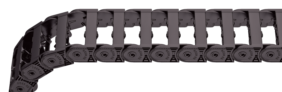
Design 040 is not suitable for gliding arrangements.
t
[mm]
|
hi
[mm]
|
hG
[mm]
|
Bk
[mm]
|
qk
[kg/m]
|
|---|---|---|---|---|
| 32 | 18 | 25,5 | Bi + 12 | 0,35 – 0,45 |
Bi
[mm]
| ||||
|---|---|---|---|---|
| 15 | 25 | 38 | 50 | 65 |
KR
[mm]
| |||||
|---|---|---|---|---|---|
| 28 | 38 | 48 | 75 | 100 | 125 |

ET0320
040
50
100
1280
VS
The divider system is mounted on every 2nd chain link as a standard. As a standard, dividers or the complete divider system (dividers with height separations) are movable in the cross section (Version A).
| Verzia |
aT min
[mm]
|
ax min
[mm]
|
ac min
[mm]
|
nT min |
|---|---|---|---|---|
| A | 4 | 8 | 6 | – |
The dividers can be moved in the cross section.

TS0
A
3
Please state the designation of the divider system (TS0), the version, and the number of dividers per cross section [nT]. You can add a sketch to your order.
The plastic end connectors can be connected from above or below. The connection type can be changed by altering the position of the end connector.


Bi [mm] | BEF [mm] | nz |
|---|---|---|
15 | 27 | 2 |
25 | 37 | 3 |
38 | 50 | 4 |
50 | 62 | 5 |
65 | 77 | 6 |


F – fixed point
M – driver
A – threaded joint outside (standard)
I – threaded joint inside
H – threaded joint, rotated 90° to the outside
K – threaded joint, rotated 90° to the inside
End connector
F
A
End connector
M
A
End connector
End connector
F
M
A
A
Spoľahlivý, robustný s vysokou dostupnosťou. Profitujte z dlhoročných skúseností a z priebežnej optimalizácie overenou počas testov i v praxi. TRAXLINE® vodiče pre kompetentné systémové poradenstvo ako aj servis po celom svete.
na TRAXLINE®Od samostatných vedení až po komplexné systémy pripravené na zapojenie, v počte 1 až po série - po celom svete sú v nasadení tisícky osvedčených systémov. Prednosti TOTALTRAX® systémov sú zjavné: jedna kontaktná osoba, jedno objednávacie číslo, dodávka just in time na želané miesto, krátke prestoje vďaka Plug & Play montáži.
na TOTALTRAX®Spoľahlivé odvíjanie a optimálne kĺzanie pri dlhých pojazdoch
na Podporné kanályNa optimálne umiestnenie pri dynamickom použití káblov
k Odľahčenie v ťahuKonštrukčné smernice:
Aktuálny informačný leták TSUBAKI KABELSCHLEPP :
 Svetlá výška
 Vonkajšia výška
 Svetlá šírka
 Vonkajšia šírka
 Svetlá šírka (Bi) v x mm šírka mriežky
 Delenie
 Polomer ohybu
 Dlhý pojazd
 Samonosná dĺžka
 Klzná dĺžka
 Veľké dodatočné zaťaženie
 Vysoké zrýchlenie
 Vysoká rýchlosť
 Deliace priečky v každom druhom článku
 Deliace priečky v každom článku
 neotvárateľné
 otvárateľné zvonka
 otvárateľné zvonka
 otvárateľné zvnútra
 otvárateľné zvnútra
 otvárateľné zvnútra / zvonka
 zakrytovaný nosič energie
 posúvateľné priečky
 polohovateľné priečky
 polohovateľné priečky v x mm mriežke
 výškové delenie možné
 výškové delenie v 1mm mriežke
 K dispozícii je mostík
 vodiaci kanál potrebný
 odľahčenie v ťahu
 vhodné do čistých priestorov
 pokojný chod / tichý chod
 metrový tovar
 Nízka hmotnosť
 Valivý nosič
 ESD materiál
 materiál na ochranu voči výbuchu
 odolný voči teplu
 odolný voči chladu
 odolný voči horúcim trieskam
 nehorľavý V0 (UL94)
 nehorľavý V2 (UL94)


