


hore 

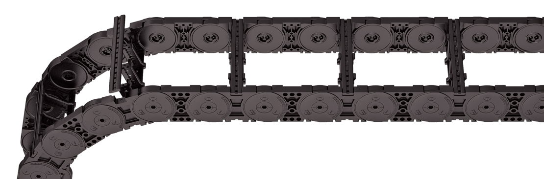

Stay arrangement on every 2nd chain link, standard (HS: half-stayed)

Stay arrangement on each chain link (VS: fully-stayed)


The maximum cable diameter strongly depends on the bending radius and the desired cable type.
Please contact us.
For rough environmental conditions, we recommend the use of OFFROAD glide shoes with 80 % higher wear volume.
t
[mm]
|
hi
[mm]
|
hG
[mm]
|
hG'
[mm]
|
hG' Offroad
[mm]
|
Bk
[mm]
|
BEF
[mm]
|
qk
[kg/m]
|
|---|---|---|---|---|---|---|---|
| 125 | 72 | 96 | 99,5 | 103 | Bi + 45 | Bi + 45 | 4,30 – 5,80 |
Bi
[mm]
| ||||||||||||||||||||||||||||||
|---|---|---|---|---|---|---|---|---|---|---|---|---|---|---|---|---|---|---|---|---|---|---|---|---|---|---|---|---|---|---|
| 71 | 87 | 103 | 119 | 135 | 151 | 167 | 183 | 199 | 215 | |||||||||||||||||||||
| 231 | 247 | 263 | 279 | 295 | 311 | 327 | 343 | 359 | 375 | |||||||||||||||||||||
| 391 | 407 | 423 | 439 | 455 | 471 | 487 | 503 | 519 | 535 | |||||||||||||||||||||
| 551 | ||||||||||||||||||||||||||||||
KR
[mm]
| ||||||
|---|---|---|---|---|---|---|
| 180 | 220 | 260 | 300 | 340 | 380 | 500 |

ME1250
407
RE
300
4250
HS
The divider system is mounted on every 2nd chain link as a standard. As a standard, dividers or the complete divider system (dividers with height separations) are movable in the cross section (version A).
The dividers are easily attached to the stay for applications with lateral acceleration and for applications laying on their side by simply turning the frame stay by 180°. The arresting cams click into place in the locking grids in the crossbars (Version B). The groove in the frame stay faces outwards.
| Verzia |
aT min
[mm]
|
ax min
[mm]
|
ac min
[mm]
|
ax Mriežka
[mm]
|
nT min |
|---|---|---|---|---|---|
| A | 5 | 14,5 | 6,5 | – | – |
| B | 19,5 | 16 | 8 | 16 | – |
The dividers can be moved within the cross section (version A) or fixed (version B).

| Verzia |
aT min
[mm]
|
aT max
[mm]
|
ax min
[mm]
|
ac min
[mm]
|
ax Mriežka
[mm]
|
nT min |
|---|---|---|---|---|---|---|
| A | 5 | 25 | 14,5 | 6,5 | – | 2 |
| B | 19,5 | 19,5 | 16 | 8 | 16 | 2 |
The dividers can be moved within the cross section (version A) or fixed (version B).

| Verzia |
aT min
[mm]
|
ax min
[mm]
|
ac min
[mm]
|
ax Mriežka
[mm]
|
nT min |
|---|---|---|---|---|---|
| A | 5 | 14,5*/20 | 6,5*/12 | – | 2 |
| B | 19,5 | 16*/32 | 8*/24 | 16 | 2 |
* for VR0
With grid distribution (16 mm grid). The dividers are fixed by the height separation, the complete divider system is movable in the cross section (version A) or fixed (version B).

| Verzia |
aT min
[mm]
|
ax min
[mm]
|
ac min
[mm]
|
nT min |
|---|---|---|---|---|
| A | 4 | 16/42* | 8 | 2 |
* for aluminum partitions
The dividers are fixed with the partitions. The entire divider system can be moved in the cross section.


Aluminum partitions with 1 mm increments with ax > 42 mm are also available.
| ax (vzdialenosť stredov deliacich priečok) [mm] | ||||||||||||||||||||||
|---|---|---|---|---|---|---|---|---|---|---|---|---|---|---|---|---|---|---|---|---|---|---|
| ac (užitočná šírka vnútornej komory) [mm] | ||||||||||||||||||||||
16 8 | 18 10 | 23 15 | 28 20 | 32 24 | 33 25 | 38 30 | 43 35 | 48 40 | 58 50 | 64 56 | 68 60 | |||||||||||
78 70 | 80 72 | 88 80 | 96 88 | 112 104 | 128 120 | 144 136 | 160 152 | 176 168 | 192 184 | 208 200 | ||||||||||||
When using plastic partitions with ax > 112 mm, we recommend an additional center support with a twin divider (ST = 4 mm). Twin dividers are also suitable for retrofitting in the partition system.
TS3
A
3
K1
K4
34
38
VR1
VR3
Please state the designation of the divider system (TS0, TS1,...), version and number of dividers per cross section [nT ]. In addition, please also enter the chambers [K] from left to right, as well as the assembly distances [aT/ax] (as seen from the driver).
If using divider systems with height separation (TS1 – TS3), please also state the positions [e.g. VD23] viewed from the left driver belt. You are welcome to add a sketch to your order.
The universal mounting brackets (UMB) are made from plastic and can be mounted from the top, from the bottom, face on or from the side.
Recommended tightening torque: 54 Nm for cheese-head screws ISO 4762 - M10 - 8.8
F – fixed point
M – driver
U – universal mounting bracket
Plastic link end connector, steel end connector. The connection variants on the fixed point and on the driver can be combined and, if required, changed afterwards.

F – fixed point
M – driver
A – threaded joint outside (standard)
I – threaded joint inside
F – flange connection
I – connection surface inside
A – connection surface outside
Plastic/steel
F
A
A
UMB
M
U
Plastic/steel
UMB
F
M
A
U
A
We recommend the use of strain reliefs at the driver and fixed point.
Spoľahlivý, robustný s vysokou dostupnosťou. Profitujte z dlhoročných skúseností a z priebežnej optimalizácie overenou počas testov i v praxi. TRAXLINE® vodiče pre kompetentné systémové poradenstvo ako aj servis po celom svete.
na TRAXLINE®Od samostatných vedení až po komplexné systémy pripravené na zapojenie, v počte 1 až po série - po celom svete sú v nasadení tisícky osvedčených systémov. Prednosti TOTALTRAX® systémov sú zjavné: jedna kontaktná osoba, jedno objednávacie číslo, dodávka just in time na želané miesto, krátke prestoje vďaka Plug & Play montáži.
na TOTALTRAX®Spoľahlivé odvíjanie a optimálne kĺzanie pri dlhých pojazdoch
na Podporné kanályNa optimálne umiestnenie pri dynamickom použití káblov
k Odľahčenie v ťahuKonštrukčné smernice:
Aktuálny informačný leták TSUBAKI KABELSCHLEPP :
 Svetlá výška
 Vonkajšia výška
 Svetlá šírka
 Vonkajšia šírka
 Svetlá šírka (Bi) v x mm šírka mriežky
 Delenie
 Polomer ohybu
 Dlhý pojazd
 Samonosná dĺžka
 Klzná dĺžka
 Veľké dodatočné zaťaženie
 Vysoké zrýchlenie
 Vysoká rýchlosť
Deliace priečky v každom druhom článku
Deliace priečky v každom článku
Vysoká rýchlosť
Deliace priečky v každom druhom článku
Deliace priečky v každom článku
 neotvárateľné
 otvárateľné zvonka
 otvárateľné zvonka
 otvárateľné zvnútra
 otvárateľné zvnútra
 otvárateľné zvnútra / zvonka
 zakrytovaný nosič energie
 posúvateľné priečky
 polohovateľné priečky
 polohovateľné priečky v x mm mriežke
 výškové delenie možné
 výškové delenie v 1mm mriežke
 K dispozícii je mostík
 vodiaci kanál potrebný
 odľahčenie v ťahu
 vhodné do čistých priestorov
 pokojný chod / tichý chod
 metrový tovar
 Nízka hmotnosť
 Valivý nosič
 ESD materiál
 materiál na ochranu voči výbuchu
 odolný voči teplu
 odolný voči chladu
 odolný voči horúcim trieskam
 nehorľavý V0 (UL94)
 nehorľavý V2 (UL94)


