


-
-
enFurther countries
 International (EN)

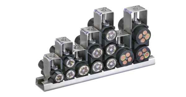


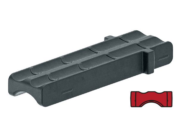
The data for the total height are guide values. The actual height depends on the cable diameter and the cable structure, among other things.
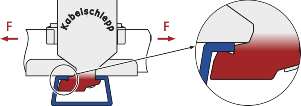
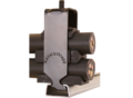
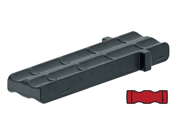
In practical operation, tensile forces occur in both cable directions. Clamps therefore have to transmit high tensile forces in the respective direction.
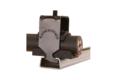
In contrast to standard commercial clamps, the LineFix® foot geometry ensures transmission of extremely high tensile forces equally in both directions. The catch fixes the foot securely in the C-profile when it is bolted on, preventing the crossbar from tipping out during load application, regardless of the direction of forces or installation.
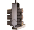
The curved support ribs fix the cables very gently and reliably.

For cable carriers with upper run gliding on the lower run, the system height of the strain relief must not be higher than the chain link height!
| Type | Designation | Material no. for one complete LineFix® | Material no. for one complete stainless steel LineFix® (ER 1S) | for cable Ø [mm] | No. of cables | Width [mm] | Total height with max. cable diam. incl. C-rail* [mm] |
|---|---|---|---|---|---|---|---|
| Single clamp | |||||||
 | LF 12-1 | 13630 | 13731 | > 6.0 – 12.0 | 1 | 16 | 55 |
| LF 14-1 | 13631 | 13732 | > 12.0 – 14.0 | 1 | 18 | 52 | |
| LF 16-1 | 13632 | 13733 | > 14.0 – 16.0 | 1 | 20 | 54 | |
| LF 18-1 | 13633 | 13734 | > 16.0 – 18.0 | 1 | 22 | 56 | |
| LF 20-1 | 13634 | 13735 | > 18.0 – 20.0 | 1 | 24 | 59 | |
| LF 22-1 | 13635 | 13736 | > 20.0 – 22.0 | 1 | 26 | 61 | |
| LF 26-1 | 13636 | 13737 | > 22.0 – 26.0 | 1 | 30 | 70 | |
| LF 30-1 | 13637 | 13738 | > 26.0 – 30.0 | 1 | 34 | 74 | |
| LF 34-1 | 13638 | 13739 | > 30.0 – 34.0 | 1 | 38 | 78 | |
| LF 38-1 | 13639 | 13740 | > 34.0 – 38.0 | 1 | 42 | 82 | |
| LF 42-1 | 13640 | 13741 | > 38.0 – 42.0 | 1 | 46 | 91 | |
| Double clamp | |||||||
 | LF 12-2 | 13641 | 13742 | > 6.0 – 12.0 | 2 | 16 | 73 |
| LF 14-2 | 13642 | 13743 | > 12.0 – 14.0 | 2 | 18 | 74 | |
| LF 16-2 | 13643 | 13744 | > 14.0 – 16.0 | 2 | 20 | 82 | |
| LF 18-2 | 13644 | 13745 | > 16.0 – 18.0 | 2 | 22 | 86 | |
| LF 20-2 | 13645 | 13746 | > 18.0 – 20.0 | 2 | 24 | 91 | |
| LF 22-2 | 13646 | 13747 | > 20.0 – 22.0 | 2 | 26 | 95 | |
| LF 26-2 | 13647 | 13748 | > 22.0 – 26.0 | 2 | 30 | 108 | |
| LF 30-2 | 13648 | 13749 | > 26.0 – 30.0 | 2 | 34 | 121 | |
| LF 34-2 | 13649 | 13750 | > 30.0 – 34.0 | 2 | 38 | 129 | |
| Triple clamp | |||||||
 | LF 12-3 | 13650 | 13751 | > 6.0 – 12.0 | 3 | 16 | 98 |
| LF 14-3 | 13651 | 13752 | > 12.0 – 14.0 | 3 | 18 | 98 | |
| LF 16-3 | 13652 | 13753 | > 14.0 – 16.0 | 3 | 20 | 105 | |
| LF 18-3 | 13653 | 13754 | > 16.0 – 18.0 | 3 | 22 | 111 | |
| LF 20-3 | 13654 | 13755 | > 18.0 – 20.0 | 3 | 24 | 118 | |
| LF 22-3 | 13655 | 13756 | > 20.0 – 22.0 | 3 | 26 | 130 | |
* Item no. 3934
Additional sizes on request.
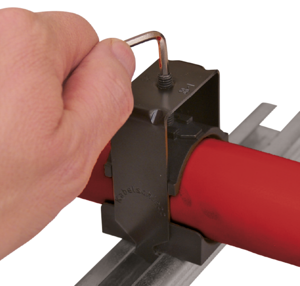
Recommended tightening torque: max. 3 Nm for electric cables suitable for cable carriers.
The standard sets of LineFix® clamps in size LF/LFX 12 offer even more flexibility and mounting options due to the extension with the new double and counter jaws. Optimized for different cable diameters and individually combinable heights, almost all requirements can be implemented without any problems.
Double jaw
LD12 d6s12
Double jaw
LD12 d6d6

Counter jaw
LG12 d6

| Material no. for one complete LineFix® | Material no. for one complete stainless steel LineFix® (ER 1S) | cable diam. Ø A [mm] | cable diam. Ø B [mm] | No. of cables | Width [mm] | Total height with max. cable diam. incl. C-profile* [mm] | |
|---|---|---|---|---|---|---|---|
| 1 | 13757 | 13773 | 3-6 (2x) | - | 2 | 16 | 51 |
| 2 | 13758 | 13774 | 3-6 (4x) | - | 4 | 16 | 70 |
| 3 | 13759 | 13775 | 3-6 (2x) | 6-12 (1x) | 3 | 16 | 74 |
| 4 | 13760 | 13776 | 3-6 (2x) | 6-12 (1x) | 3 | 16 | 70 |
| 5 | 13761 | 13777 | 3-6 (6x) | - | 6 | 16 | 89 |
| 6 | 13762 | 13778 | 3-6 (4x) | 6-12 (1x) | 5 | 16 | 94 |
| 7 | 13763 | 13779 | 3-6 (4x) | 6-12 (1x) | 5 | 16 | 94 |
| 8 | 13764 | 13780 | 3-6 (2x) | 6-12 (2x) | 4 | 16 | 98 |
| 9 | 13765 | 13781 | 3-6 (8x) | - | 8 | 16 | 98 |
| 10 | 13766 | 13782 | 3-6 (6x) | 6-12 (1x) | 7 | 16 | 103 |
| 11 | 13767 | 13783 | 3-6 (6x) | 6-12 (1x) | 7 | 16 | 103 |
| 12 | 13768 | 13784 | 3-6 (6x) | 6-12 (1x) | 7 | 16 | 103 |
| 13 | 13769 | 13785 | 3-6 (6x) | 6-12 (1x) | 7 | 16 | 98 |
| 14 | 13770 | 13786 | 3-6 (4x) | 6-12 (2x) | 6 | 16 | 103 |
| 15 | 13771 | 13787 | 3-6 (4x) | 6-12 (2x) | 6 | 16 | 103 |
| 16 | 13772 | 13788 | 3-6 (4x) | 6-12 (2x) | 6 | 16 | 102 |
* Material-Nr. 3934
Reliable, robust with high availability. Your benefit from many years of experience combined with ongoing optimization, proven in tests and praxis. TRAXLINE® cables stand for competent system-supply with worldwide on-site service.
to TRAXLINE®From pre-assembled cables to complex, ready-to-connect systems, from lot size 1 to series – worldwide thousands of KABELSCHLEPP systems are reliably in use. The benefits of TOTALTRAX® systems are obvious: just one person of contact, one order number, delivery just-in-time to your production facility, shortest downtimes thanks to plug&play installation.
to TOTALTRAX®Reliable unrolling and optimum gliding for long travel lengths
to Support traysFor optimum placement with dynamic use of cables
to Strain relief devicesConfiguration guidelines:
The latest TSUBAKI KABELSCHLEPP information material:
Our product filter supports you in finding the right cable carrier. Simply select your desired parameters and you will quickly get an overview of all suitable type series.
 Inner height
 Outer height
 Inner width
 Outer width
 Inner width (Bi) in x mm increments
 Pitch
Pitch
 Bending radius
 Long travel length
 Travel length unsupported
 Travel length gliding
 High additional load
 High travel acceleration
 High travel velocity
 Stay arrangement on every 2nd chain link
 Stay arrangement on every chain link
 Cannot be opened
 Opens outward
 Opens outward
 Opens inward
 Opens inward
 Opens inward/outward
 Covered cable carrier
 Sliding dividers
 Fixable dividers
 Fixable dividers in x mm grid
 Height separation possible
 Height separation in 1 mm increments
 Hole stay available
 Guide channel required
 Strain relief
 Clean room suitable
 Quiet running/low noise
 Sold by the meter
 Low weight
 Roller chain
 ESD material
 Ex-protection-material
 Heat-resistant
 Cold-resistant
 Resistant to hot chips
 Flame-resistant V0 (UL94)
 Flame-resistant V2 (UL94)


