


-
-
enFurther countries
 International (EN)


The maximum cable diameter strongly depends on the bending radius and the desired cable type. Please contact us.
t
[mm]
|
hi
[mm]
|
hG
[mm]
|
Bk
[mm]
|
qk
[kg/m]
|
|---|---|---|---|---|
| 45.5 | 36 | 51 | Bi + 16 | 1.34 – 2.29 |
Bi
[mm]
| ||||
|---|---|---|---|---|
| 50 | 75 | 100 | 125 | 150 |
KR
[mm]
| ||||||
|---|---|---|---|---|---|---|
| 82 | 95 | 125 | 145 | 170 | 200 | 230 |

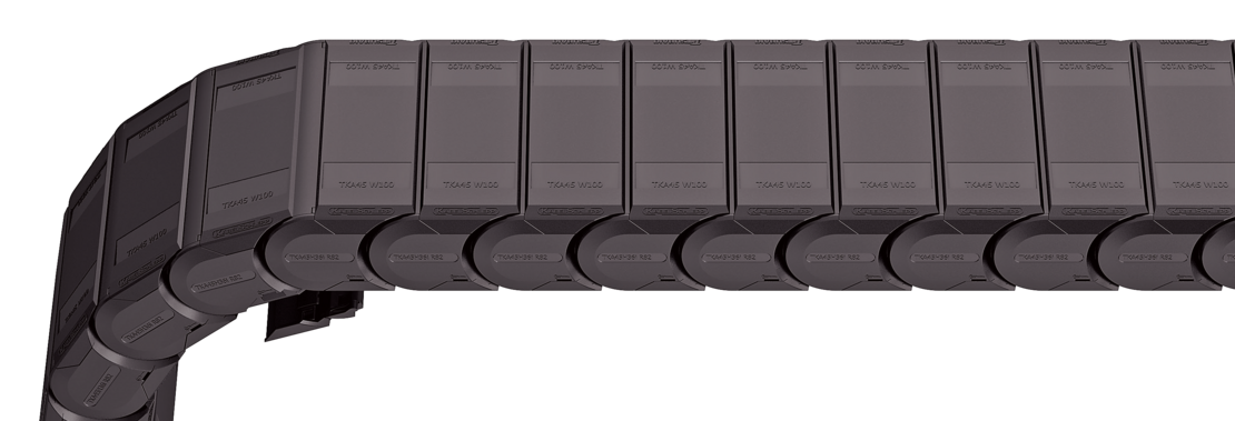
TKA45
060
125
170
1456
VS
The divider system is mounted on every 2nd chain link as a standard. As a standard, dividers or the complete divider system (dividers with height separations) are movable in the cross section (Version A).
The dividers are easily attached to the stay for applications with transverse accelerations and for applications laying on the side by simply turning them.
The locking cams click into place in the locking grids in the covers (Version B).
| Vers. |
aT min
[mm]
|
ax min
[mm]
|
ac min
[mm]
|
ax grid
[mm]
|
nT min |
|---|---|---|---|---|---|
| A | 4 | 8 | 5.5 | – | – |
| B | A | 8 | 5.5 | 2 | – |
| A | Bi [mm]
aT min [mm]
| 50 11 | 75 11.5 | 100 12 | 125 12.5 | 150 11 |

| Vers. |
aT min
[mm]
|
ax min
[mm]
|
ac min
[mm]
|
ax grid
[mm]
|
nT min |
|---|---|---|---|---|---|
| A | 4 | 8 | 5.5 | – | 2 |
| B | A | 8 | 5.5 | 2 | 2 |
| A | Bi [mm]
aT min [mm]
| 50 11 | 75 11.5 | 100 12 | 125 12.5 | 150 11 |

As a standard. the divider A is used for vertical partitioning within the cable carrier. The complete divider system can be moved within the cross section. (version A).
The dividers are easily attached to the stay for applications with transverse accelerations and for applications laying on the side by simply turning them.
The locking cams click into place in the locking grids in the covers (version B).
Divider version A

End divider

| Vers. |
aT min
[mm]
|
ax min
[mm]
|
ac min
[mm]
|
nT min |
|---|---|---|---|---|
| A | 4/2* | 14 | 10 | 2 |
* for End divider
The dividers are fixed by the partitions, the complete divider system is movable in the cross section.


| ax (center distance of dividers) [mm] | ||||||||||||||||||||||||||||||||
|---|---|---|---|---|---|---|---|---|---|---|---|---|---|---|---|---|---|---|---|---|---|---|---|---|---|---|---|---|---|---|---|---|
| ac (nominal width of inner chamber) [mm] | ||||||||||||||||||||||||||||||||
14 10 | 16 12 | 19 15 | 23 19 | 24 20 | 28 24 | 29 25 | 32 28 | 33 29 | 34 30 | 38 34 | 39 35 | |||||||||||||||||||||
43 39 | 44 40 | 48 44 | 49 45 | 54 50 | 58 54 | 59 55 | 64 60 | 68 64 | 69 65 | 74 70 | 78 74 | |||||||||||||||||||||
79 75 | 80 76 | 84 80 | 88 84 | 89 85 | 94 90 | 96 92 | 99 95 | 112 108 | ||||||||||||||||||||||||
When using partitions with ax > 49 mm we recommended an additional preferential central support.
TS1
A
3
VD0
VD1
Please state the designation of the divider system (TS0, TS1 …), version and number of dividers per cross section [nT].
If using divider systems with height separation (TS1), please also state the positions [e.g. VD1] viewed from the left driver belt. You are welcome to add a sketch to your order.
The universal end connectors (UMB) are made from plastic and can be mounted from the top, from the bottom, or face on.


Recommended tightening torque:
5 Nm for cheese-head screws ISO 4762 - M5 x 8.8
Bi [mm] | BEF [mm] | nz |
|---|---|---|
50 | 70 | 2 x 3 |
75 | 95 | 2 x 5 |
100 | 120 | 2 x 7 |
125 | 145 | 2 x 9 |
150 | 170 | 2 x 11 |

The end connectors are also available as an option without cover sheets. Please state when ordering.

F – fixed point
M – driver
U – universal end connector
UMB
F
U
UMB
M
U
UMB
UMB
F
M
U
U
Reliable, robust with high availability. Your benefit from many years of experience combined with ongoing optimization, proven in tests and praxis. TRAXLINE® cables stand for competent system-supply with worldwide on-site service.
to TRAXLINE®From pre-assembled cables to complex, ready-to-connect systems, from lot size 1 to series – worldwide thousands of KABELSCHLEPP systems are reliably in use. The benefits of TOTALTRAX® systems are obvious: just one person of contact, one order number, delivery just-in-time to your production facility, shortest downtimes thanks to plug&play installation.
to TOTALTRAX®Reliable unrolling and optimum gliding for long travel lengths
to Support traysFor optimum placement with dynamic use of cables
to Strain relief devicesConfiguration guidelines:
The latest TSUBAKI KABELSCHLEPP information material:
 Inner height
 Outer height
 Inner width
 Outer width
 Inner width (Bi) in x mm increments
 Pitch
Pitch
 Bending radius
 Long travel length
 Travel length unsupported
 Travel length gliding
 High additional load
 High travel acceleration
 High travel velocity
 Stay arrangement on every 2nd chain link
 Stay arrangement on every chain link
 Cannot be opened
 Opens outward
 Opens outward
 Opens inward
 Opens inward
 Opens inward/outward
 Covered cable carrier
 Sliding dividers
 Fixable dividers
 Fixable dividers in x mm grid
 Height separation possible
 Height separation in 1 mm increments
 Hole stay available
 Guide channel required
 Strain relief
 Clean room suitable
 Quiet running/low noise
 Sold by the meter
 Low weight
 Roller chain
 ESD material
 Ex-protection-material
 Heat-resistant
 Cold-resistant
 Resistant to hot chips
 Flame-resistant V0 (UL94)
 Flame-resistant V2 (UL94)


