


-
-
enFurther countries
 International (EN)


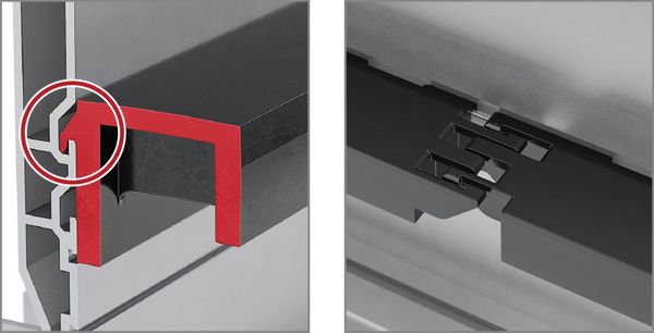
Channel side wall
Al alloy

Standard lengths 1000 / 2000 mm
Special lengths on request
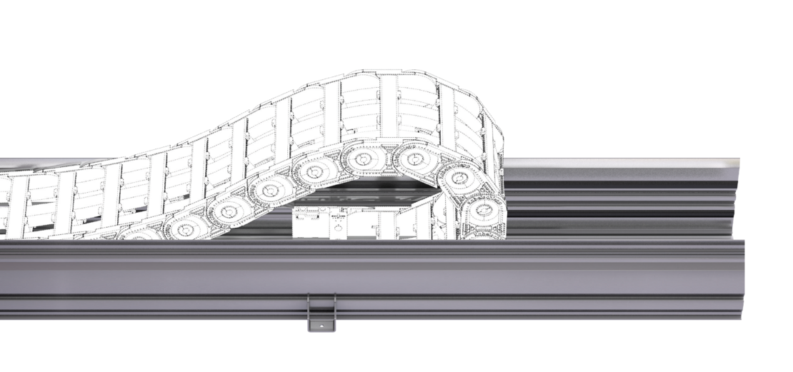
The Alu Guide System (TKAL) for long travel applications and high loads ensures secure guidance and smooth running of the energy chain in a gliding and rolling application.
The standardized channel profiles of 1000 / 2000 mm in length can be individually adjusted to the width of the chain. They can be quickly and easily be installed with the help of a mounting kit. Such UMB mounting kits are also available for attaching the fixed-point of the energy chain.
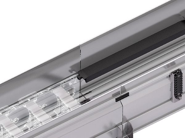
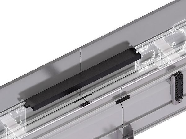
The optional damping band additionally reduces noise emission and guarantees an even quieter running of the chain.
TSUBAKI KABELSCHLEPP also offer the Alu Guide System (TKAL) together with the appropriate energy chain as well as with the ready-to-install TOTALTRAX® System including cables.
For One-sided arrangement of the cable carrier, the cable carrier slides behind the fixed point on a slide support with run-on bevels.
Channel profile with and without supports incl. run-on bevels.
Dirt and water can drop through without restrictions.
Channel profile with and without supports incl. run-on bevels.
Dirt and water can drop through without restrictions.
For opposite arrangement, a slide support with a minimum length of 500 mm is also attached for bridging between the fixed point connections.
Channel profile with and without supports incl. run-on bevels.
Dirt and water can drop through without restrictions.
Channel profile with and without supports incl. run-on bevels.
Dirt and water can drop through without restrictions.

TKAL 134

TKAL 195

TKAL 254

TKAL 274
* for C-profiles 3938/3939
** for C-profiles 3940/3941

TKAL 134: Using holder inside double-sided b1 min.: 118 mm – Using holder outside double-sided b1 min.: 50 mm – C-profile length LP rounded to 50 mm
TKAL 195: Using holder inside double-sided b1 min.: 134 mm – Using holder outside double-sided b1 min.: 90 mm – C-profile length LP rounded to 50 mm
TKAL 254: Using holder inside double-sided b1 min.: 134 mm – Using holder outside double-sided b1 min.: 90 mm – C-profile length LP rounded to 50 mm
TKAL 274: Using holder inside double-sided b1 min.: 146 mm – Using holder outside double-sided b1 min.: 90 mm – C-profile length LP rounded to 50 mm
As a standard, the mounting kits included with the delivery are installed on all joins as well as at both ends of a channel. If you require more angle brackets beyond this, please state this when ordering.
The cable carrier outer width without attachments Bk is taken into account for calculating the inner width of guide channel b1 and the overall width BKA.
| Type | h1 [mm] | hKA [mm] | b1 [mm] | b2 [mm] | b3 [mm] | BKA [mm] | T [mm] | ||||
|---|---|---|---|---|---|---|---|---|---|---|---|
| UA1455 | |||||||||||
| Glide shoes | 40 | 134 | Bk + 7 | Bk + 50 | Bk + 69 | BK + 25 | 25 | ||||
| UA1555 | |||||||||||
| Glide shoes | 53 | 134 | Bk + 9 | Bk + 52 | Bk + 67 | BK + 27 | 25 | ||||
| UA1665 | |||||||||||
| Glide shoes | 61.5 | 195 | Bk + 10 | Bk + 60.15 | Bk + 82.4 | BK + 28.6 | 45 | ||||
| UA1775 | |||||||||||
| Glide shoes | 81 | 195 | Bk + 9 | Bk + 59.15 | Bk + 83.4 | BK + 27.6 | 45 | ||||
| UA1995 | |||||||||||
| Glide shoes | 116 | 254 | Bk + 10.4 | Bk + 71.9 | Bk + 81 | BK + 45 | 45 | ||||
The cable carrier outer width without attachments Bk is taken into account for calculating the inner width of guide channel b1 and the overall width BKA.
| Type | h1 [mm] | hKA [mm] | b1 [mm] | b2 [mm] | b3 [mm] | BKA [mm] | T [mm] | ||||
|---|---|---|---|---|---|---|---|---|---|---|---|
| K0650 | |||||||||||
| – | 56.5 | 134 | Bk + 5 | Bk + 48 | Bk + 71 | BK + 23 | 25 | ||||
| Slide discs | 56.5 | 134 | Bk + 13 | Bk + 56 | Bk + 63 | BK + 31 | 25 | ||||
| K0900 | |||||||||||
| – | 81 | 195 | Bk + 5 | Bk + 55.15 | Bk + 87.4 | BK + 23.6 | 25 | ||||
| Slide discs | 81 | 195 | Bk + 19 | Bk + 69.15 | Bk + 73.4 | BK + 37.6 | 45 | ||||
The cable carrier outer width without attachments Bk is taken into account for calculating the inner width of guide channel b1 and the overall width BKA.
| Type | h1 [mm] | hKA [mm] | b1 [mm] | b2 [mm] | b3 [mm] | BKA [mm] | T [mm] | ||||
|---|---|---|---|---|---|---|---|---|---|---|---|
| M0650 | |||||||||||
| Glide shoes | 61.5 | 195 | Bk + 5 | Bk + 55.15 | Bk + 87.4 | BK + 23.6 | 45 | ||||
| Offroad Glide shoes | 61.5 | 195 | Bk + 5 | Bk + 55.15 | Bk + 87.4 | BK + 23.6 | 45 | ||||
| M0950 | |||||||||||
| Glide shoes | 81 | 195 | Bk + 5 | Bk + 55.15 | Bk + 87.4 | BK + 23.6 | 45 | ||||
| Offroad Glide shoes | 86 | 195 | Bk + 5 | Bk + 55.15 | Bk + 87.4 | BK + 23.6 | 45 | ||||
| M1250 | |||||||||||
| Offroad Glide shoes | 103 | 274 | Bk + 6 | Bk + 67.5 | Bk + 97.4 | BK + 40.6 | 45 | ||||
| M1300 | |||||||||||
| Glide shoes | 127.5 | 274 | Bk + 6 | Bk + 67.5 | Bk + 97.4 | BK + 40.6 | 45 | ||||
The cable carrier outer width without attachments Bk is taken into account for calculating the inner width of guide channel b1 and the overall width BKA.
| Type | Design | h1 [mm] | hKA [mm] | b1 [mm] | b2 [mm] | b3 [mm] | BKA [mm] | T [mm] | |||
|---|---|---|---|---|---|---|---|---|---|---|---|
| TKHP85 | |||||||||||
| Glide shoes | 254 | 90 | 254 | Bk + 6 | Bk + 67.5 | Bk + 85.4 | BK + 40.6 | 45 | |||
| TKHP90 | |||||||||||
| Glide shoes | 274 | 127.5 | 274 | Bk + 6 | Bk + 67.5 | Bk + 97.4 | BK + 40.6 | 45 | |||
| TKHP85-R + TKHP85-RSD | |||||||||||
| – | 254 | 84.5 | 254 | Bk + 6 | Bk + 67.5 | Bk + 85.4 | BK + 40.6 | 45 | |||
| TKHP90-R + TKHP90-RSD | |||||||||||
| – | 274 | 117 | 274 | Bk + 6 | Bk + 67.5 | Bk + 97.4 | BK + 40.6 | 45 | |||
The cable carrier outer width without attachments Bk is taken into account for calculating the inner width of guide channel b1 and the overall width BKA.
| Type | h1 [mm] | hKA [mm] | b1 [mm] | b2 [mm] | b3 [mm] | BKA [mm] | T [mm] | ||||
|---|---|---|---|---|---|---|---|---|---|---|---|
| Q040 | |||||||||||
| – | 40 | 134 | Bk + 4 | Bk + 47 | Bk + 72 | BK + 22 | 25 | ||||
| Q060 | |||||||||||
| Glide shoes | 66.5 | 195 | Bk + 9 | Bk + 59.15 | Bk + 83.4 | BK + 27.6 | 45 | ||||
| Q080 | |||||||||||
| Glide shoes | 86 | 195 | Bk + 13 | Bk + 63.15 | Bk + 79.4 | BK + 31.6 | 45 | ||||
| Q100 | |||||||||||
| Glide shoes | 108 | 274 | Bk + 13 | Bk + 74.5 | Bk + 90.4 | BK + 47.6 | 45 | ||||
The cable carrier outer width without attachments Bk is taken into account for calculating the inner width of guide channel b1 and the overall width BKA.
| Type | h1 [mm] | hKA [mm] | b1 [mm] | b2 [mm] | b3 [mm] | BKA [mm] | T [mm] | ||||
|---|---|---|---|---|---|---|---|---|---|---|---|
| TKA38 | |||||||||||
| – | 36.5 | 134 | Bk + 4 | Bk + 47 | Bk + 72 | BK + 22 | 25 | ||||
| TKA45 | |||||||||||
| – | 53 | 134 | Bk + 5 | Bk + 48 | Bk + 71 | BK + 23 | 25 | ||||
| TKA55 | |||||||||||
| – | 66.5 | 195 | Bk + 5 | Bk + 55.15 | Bk + 87.4 | BK + 23.6 | 45 | ||||
The cable carrier outer width without attachments Bk is taken into account for calculating the inner width of guide channel b1 and the overall width BKA.
| Type | h1 [mm] | hKA [mm] | b1 [mm] | b2 [mm] | b3 [mm] | BKA [mm] | T [mm] | ||||
|---|---|---|---|---|---|---|---|---|---|---|---|
| UAT1555 | |||||||||||
| – | 66.5 | 195 | Bk + 5 | Bk + 55.15 | Bk + 87.4 | BK + 23.6 | 45 | ||||
TKAL 134: Using holder inside double-sided b1 min.: 118 mm – Using holder outside double-sided b1 min.: 50 mm – C-profile length LP rounded to 50 mm
TKAL 195: Using holder inside double-sided b1 min.: 134 mm – Using holder outside double-sided b1 min.: 90 mm – C-profile length LP rounded to 50 mm
TKAL 254: Using holder inside double-sided b1 min.: 134 mm – Using holder outside double-sided b1 min.: 90 mm – C-profile length LP rounded to 50 mm
TKAL 274: Using holder inside double-sided b1 min.: 146 mm – Using holder outside double-sided b1 min.: 90 mm – C-profile length LP rounded to 50 mm
As a standard, the mounting kits included with the delivery are installed on all joins as well as at both ends of a channel. If you require more angle brackets beyond this, please state this when ordering.
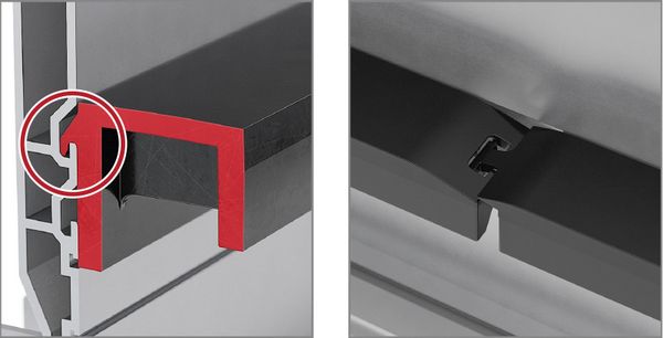
The internal or external mounting kits made of stainless steel are mounted at the joints, ensuring precise connection of the joints in addition to fastening the channel to the substructure.
The internal and external mounting kits made of stainless steel are mounted with a spacing of 30-500 mm from the joints, ensuring fastening of the channel to the substructure. The mounting kit does not necessarily have to be mounted at the joints.

* More information can be found on page assembly profiles for guide channels.

The mounting brackets are mounted at the outside of the channel.
The additional joint connectors ensure precise connection of the joints.

The mounting brackets are mounted at the inside of the channel.
The additional joint connectors ensure precise connection of the joints.

UMB mounting kit
The UMB mounting kit for fixed point ensures optimum fastening of the cable carrier in the channel and depends on the cable carrier type.

Holder set strain relief (optional)
The holders are mounted on the outside of the channel for fixed installation of cables.

The twin channel connectors enable the parallel arrangement of several channels.
All pictures of the mounting kit are exemplary.
To order the Alu Guide System, please provide the following information or the used cable carrier:
Reliable, robust with high availability. Your benefit from many years of experience combined with ongoing optimization, proven in tests and praxis. TRAXLINE® cables stand for competent system-supply with worldwide on-site service.
to TRAXLINE®From pre-assembled cables to complex, ready-to-connect systems, from lot size 1 to series – worldwide thousands of KABELSCHLEPP systems are reliably in use. The benefits of TOTALTRAX® systems are obvious: just one person of contact, one order number, delivery just-in-time to your production facility, shortest downtimes thanks to plug&play installation.
to TOTALTRAX®Reliable unrolling and optimum gliding for long travel lengths
to Support traysFor optimum placement with dynamic use of cables
to Strain relief devicesConfiguration guidelines:
The latest TSUBAKI KABELSCHLEPP information material:
Our product filter supports you in finding the right cable carrier. Simply select your desired parameters and you will quickly get an overview of all suitable type series.
 Inner height
 Outer height
 Inner width
 Outer width
 Inner width (Bi) in x mm increments
 Pitch
Pitch
 Bending radius
 Long travel length
 Travel length unsupported
 Travel length gliding
 High additional load
 High travel acceleration
 High travel velocity
 Stay arrangement on every 2nd chain link
 Stay arrangement on every chain link
 Cannot be opened
 Opens outward
 Opens outward
 Opens inward
 Opens inward
 Opens inward/outward
 Covered cable carrier
 Sliding dividers
 Fixable dividers
 Fixable dividers in x mm grid
 Height separation possible
 Height separation in 1 mm increments
 Hole stay available
 Guide channel required
 Strain relief
 Clean room suitable
 Quiet running/low noise
 Sold by the meter
 Low weight
 Roller chain
 ESD material
 Ex-protection-material
 Heat-resistant
 Cold-resistant
 Resistant to hot chips
 Flame-resistant V0 (UL94)
 Flame-resistant V2 (UL94)


