


-
-
enFurther countries
 International (EN)


Zinc plated sheet steel / stainless steel

Standard lengths 2000 / 3000 mm
Special lengths on request
We can also manufacture customized sheet steel guide channels for your application, taking into account virtually any request regarding customized shapes and fixing options.
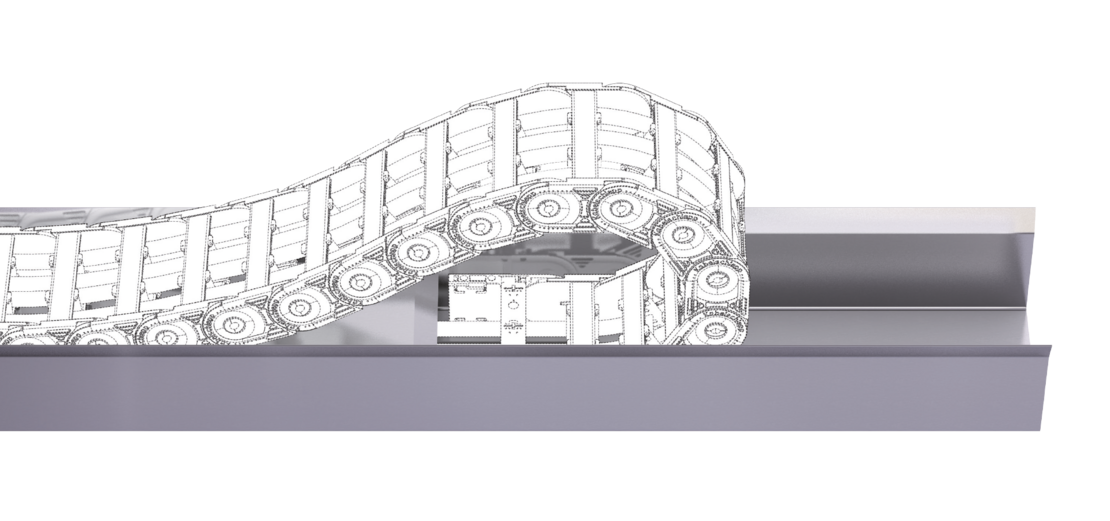
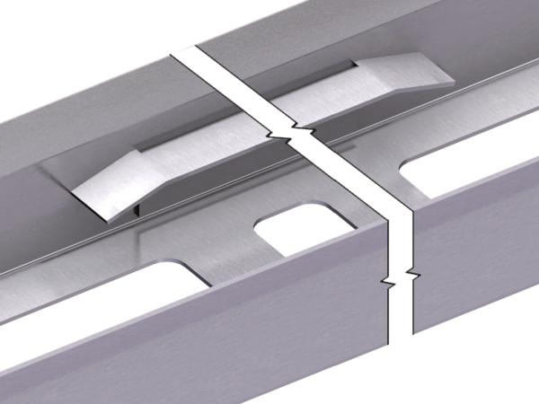
For one-sided arrangement of the cable carrier, the cable carrier slides behind the fixed point on a continuous slide support with run-on bevels.
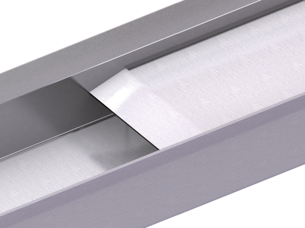
One part channel closed at the bottom and one part slide support with run-on bevels.
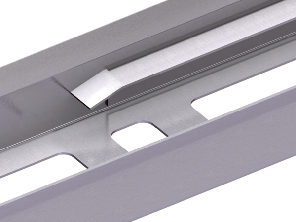
One part channel closed at the bottom and divided slide support with run-on bevels.
Dirt and liquids can drop through without restrictions.
One part channel closed at the bottom and one part slide support with run-on bevels.
One part channel closed at the bottom and divided slide support with run-on bevels.
Dirt and liquids can drop through without restrictions.
For opposite arrangement, a slide support is also attached for bridging between the fixed point connections.
One part channel closed at the bottom and one part slide support with run-on bevels.
One part channel closed at the bottom and divided slide support with run-on bevels.
Dirt and liquids can drop through without restrictions.
One part channel closed at the bottom and one part slide support with run-on bevels.
One part channel closed at the bottom and divided slide support with run-on bevels.
Dirt and liquids can drop through without restrictions.

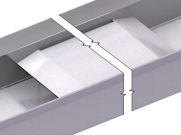
A special slide support can be adhered to reduce sliding resistance and abrasion between cable carrier and support. We recommend the use of special slide supports for velocities > 0.5 m/s and for frequent move cycles.


From hKA ≥ 200 mm, the guide channel flanks are additionally stabilized with alignment flanges or with connecting flanges.
The dimension y refers only to open guide channel versions.
The cable carrier outer width without attachments Bk is taken into account for calculating the inner width of guide channel b1 and the overall width BKA.
| Type | h1 [mm] | hKA [mm] | b1 [mm] | BKA [mm] | s [mm] | A [mm] | B [mm] | C [mm] | D [mm] | T [mm] | Y [mm] |
|---|---|---|---|---|---|---|---|---|---|---|---|
| UA1455 | |||||||||||
| – | 36 |
70 (KR < 100) 125 (KR ≥ 100) | Bk + 4 | BK + 24 | 2 | b1 – 34 (FA-A) | – | 40 | 6.2 | 30 | b1 – 65 |
| – | 36 |
70 (KR < 100) 125 (KR ≥ 100) | Bk + 4 | BK + 24 | 2 | b1 – 34.5 (FA-L) | – | 40 | 6.2 | 30 | b1 – 65 |
| – | 36 |
70 (KR < 100) 125 (KR ≥ 100) | Bk + 7 | BK + 24 | 2 | b1 – 13.5 (FU) | – | 50 | 5.3 | 30 | b1 – 40 |
| Glide shoes | 38.5 |
70 (KR < 100) 125 (KR ≥ 100) | Bk + 7 | BK + 27 | 2 | b1 – 37 (FA-A) | – | 40 | 6.2 | 30 | b1 – 65 |
| Glide shoes | 38.5 |
70 (KR < 100) 125 (KR ≥ 100) | Bk + 7 | BK + 27 | 2 | b1 – 37.5 (FA-L) | – | 40 | 6.2 | 30 | b1 – 65 |
| Glide shoes | 38.5 |
70 (KR < 100) 125 (KR ≥ 100) | Bk + 7 | BK + 27 | 2 | b1 – 16.5 (FU) | – | 50 | 5.3 | 30 | b1 – 40 |
| UA1555 | |||||||||||
| – | 50 |
117 (KR < 200) 200 (KR ≥ 200) | Bk + 5 | BK + 25 | 2 | b1 – 43 (FA) | – | 50 | 6.5 | 30 | b1 – 85 |
| – | 50 |
117 (KR < 200) 200 (KR ≥ 200) | Bk + 5 | BK + 25 | 2 | b1 – 16 (FU) | 22.5 | 50 | 5.3 | 30 | b1 – 40 |
| Glide shoes | 53 |
117 (KR < 200) 200 (KR ≥ 200) | Bk + 9 | BK + 29 | 2 | b1 – 47 (FA) | – | 50 | 6.5 | 30 | b1 – 85 |
| Glide shoes | 53 |
117 (KR < 200) 200 (KR ≥ 200) | Bk + 9 | BK + 29 | 2 | b1 – 21 (FU) | 22.5 | 50 | 5.3 | 30 | b1 – 40 |
| UA1665 | |||||||||||
| – | 60 |
117 (KR < 200) 200 (KR ≥ 200) | Bk + 5 | BK + 25 | 2 | b1 – 47 (FA) | – | 60 | 8.5 | 30 | b1 – 85 |
| – | 60 |
117 (KR < 200) 200 (KR ≥ 200) | Bk + 5 | BK + 25 | 2 | b1 – 14 (FU) | 22.5 | 60 | 5.3 | 30 | b1 – 40 |
| Glide shoes | 63 |
117 (KR < 200) 200 (KR ≥ 200) | Bk + 10 | BK + 30 | 2 | b1 – 52 (FA) | – | 60 | 8.5 | 30 | b1 – 85 |
| Glide shoes | 63 |
117 (KR < 200) 200 (KR ≥ 200) | Bk + 10 | BK + 30 | 2 | b1 – 19 (FU) | 22.5 | 60 | 5.3 | 30 | b1 – 40 |
| UA1775 | |||||||||||
| – | 77 |
150 (KR < 200) 300 (KR ≥ 200) | Bk + 5 | BK + 25 | 2 | b1 – 19.6 (FU) | 20 | 60 | 8.5 | 30 | b1 – 65 |
| Glide shoes | 81.5 |
150 (KR < 200) 300 (KR ≥ 200) | Bk + 10 | BK + 30 | 2 | b1 – 24.6 (FU) | 20 | 60 | 8.5 | 30 | b1 – 65 |
| UA1995 | |||||||||||
| – | 110 |
150 (KR < 200) 300 (KR ≥ 200) | Bk + 6 | BK + 26 | 2 | b1 – 28 (FU) | 35 | 60 | 8.5 | 30 | b1 – 60 |
| Glide shoes | 116.5 |
150 (KR < 200) 300 (KR ≥ 200) | Bk + 11 | BK + 31 | 2 | b1 – 28 (FU) | 35 | 60 | 8.5 | 30 | b1 – 60 |
The designations for dimension A refer to the version of the cable carrier connection.
* Dimension T for leg length support brackets (guiding channel open type for Bk ≥ 90 mm).
** Dimension Y for guiding channel open for Bk ≥ 90 mm).
| Type | h1 [mm] | hKA [mm] | b1 [mm] | BKA [mm] | s [mm] | A [mm] | B [mm] | C [mm] | D [mm] | T [mm] | Y [mm] |
|---|---|---|---|---|---|---|---|---|---|---|---|
| TKK39 | |||||||||||
| – | 50 | 117 | Bk + 5 | BK + 25 | 2 | b1 – 43 | 24 | 40 | 5.2 | 30 | b1 – 40 |
The designations for dimension A refer to the version of the cable carrier connection.
The cable carrier outer width without attachments Bk is taken into account for calculating the inner width of guide channel b1 and the overall width BKA.
When using aluminum hole stays, slide discs have to be placed on the side tabs between cable carrier and channel wall for spacing.
| Type | h1 [mm] | hKA [mm] | b1 [mm] | BKA [mm] | s [mm] | A [mm] | B [mm] | C [mm] | D [mm] | T [mm] | Y [mm] |
|---|---|---|---|---|---|---|---|---|---|---|---|
| K0650 | |||||||||||
| – | 57.5 |
117 (KR < 200) 200 (KR ≥ 200) | Bk + 5 | BK + 25 | 2 | b1 – 19 (FU) | 40 | 30 | 6.5 | 30 | b1 – 65 |
| Slide discs | 57.5 |
117 (KR < 200) 200 (KR ≥ 200) | Bk + 13 | BK + 33 | 2 | b1 – 27 (FA) | 40 | 30 | 6.5 | 30 | b1 – 65 |
| Slide discs | 57.5 |
117 (KR < 200) 200 (KR ≥ 200) | Bk + 13 | BK + 33 | 2 | b1 – 27 (FU) | 40 | 30 | 6.5 | 30 | b1 – 65 |
| K0900 | |||||||||||
| – | 78.5 |
150 (KR < 200) 300 (KR ≥ 200) | Bk + 5 | BK + 25 | 2 | b1 – 20.5 (FU) | 50 | 30 | 6.5 | 30 | b1 – 65 |
| Slide discs | 78.5 |
150 (KR < 200) 300 (KR ≥ 200) | Bk + 19 | BK + 39 | 2 | b1 – 34 (FA) | 50 | 30 | 6.5 | 30 | b1 – 75 |
| Slide discs | 78.5 |
150 (KR < 200) 300 (KR ≥ 200) | Bk + 19 | BK + 39 | 2 | b1 – 34.5 (FU) | 50 | 30 | 6.5 | 30 | b1 – 75 |
The designations for dimension A refer to the version of the cable carrier connection.
The cable carrier outer width without attachments Bk is taken into account for calculating the inner width of guide channel b1 and the overall width BKA.
For type M0320 we recommend aluminum guide channels.
| Type | h1 [mm] | hKA [mm] | b1 [mm] | BKA [mm] | s [mm] | A [mm] | B [mm] | C [mm] | D [mm] | T [mm] | Y [mm] |
|---|---|---|---|---|---|---|---|---|---|---|---|
| M0475 | |||||||||||
| Glide shoes | 41.5 |
70 (KR < 100) 125 (KR ≥ 100) | Bk + 4 | BK + 24 | 2 | b1 – 39 (FI) | 24 | 30 | 6.5 | 30 | b1 – 55 |
| M0650 | |||||||||||
| Glide shoes | 60.6 |
117 (KR < 200) 200 (KR ≥ 200) | Bk + 5 | BK + 25 | 2 | b1 – 55 (FAI) | 30 | 30 | 6.5 | 30 | b1 – 70 |
| Glide shoes | 60.6 |
117 (KR < 200) 200 (KR ≥ 200) | Bk + 5 | BK + 25 | 2 | b1 – 24 (FU) | 22.5 | 30 | 6.5 | 30 | b1 – 70 |
| Offroad Glide shoes | 62.2 |
117 (KR < 200) 200 (KR ≥ 200) | Bk + 5 | BK + 25 | 2 | b1 – 55 (FAI) | 30 | 30 | 6.5 | 30 | b1 – 65 |
| Offroad Glide shoes | 62.2 |
117 (KR < 200) 200 (KR ≥ 200) | Bk + 5 | BK + 25 | 2 | b1 – 24 (FU) | 22.5 | 30 | 6.5 | 30 | b1 – 65 |
| M0950 | |||||||||||
| Glide shoes | 83.5 |
150 (KR < 200) 300 (KR ≥ 200) | Bk + 5 | BK + 25 | 2 | b1 – 70 (FAI) | 40 | 30 | 8.5 | 30 | b1 – 100 |
| Glide shoes | 83.5 |
150 (KR < 200) 300 (KR ≥ 200) | Bk + 5 | BK + 25 | 2 | b1 – 19.5 (FU) | 35 | 30 | 8.5 | 30 | b1 – 60 |
| Offroad Glide shoes | 86 |
150 (KR < 200) 300 (KR ≥ 200) | Bk + 5 | BK + 25 | 2 | b1 – 70 (FAI) | 40 | 30 | 8.5 | 30 | b1 – 100 |
| Offroad Glide shoes | 86 |
150 (KR < 200) 300 (KR ≥ 200) | Bk + 5 | BK + 25 | 2 | b1 – 19.5 (FU) | 35 | 30 | 8.5 | 30 | b1 – 60 |
| M1250 | |||||||||||
| Glide shoes | 99.5 |
200 (KR < 300) 400 (KR ≥ 300) | Bk + 6 | BK + 26 | 3 | b1 – 83 (FAI) | 50 | 30 | 10.5 | 30 | b1 – 125 |
| Glide shoes | 99.5 |
200 (KR < 300) 400 (KR ≥ 300) | Bk + 6 | BK + 26 | 3 | b1 – 23 (FU) | 35 | 30 | 11 | 30 | b1 – 65 |
| Offroad Glide shoes | 103 |
200 (KR < 300) 400 (KR ≥ 300) | Bk + 6 | BK + 26 | 3 | b1 – 83 (FAI) | 50 | 30 | 10.5 | 30 | b1 – 125 |
| Offroad Glide shoes | 103 |
200 (KR < 300) 400 (KR ≥ 300) | Bk + 6 | BK + 26 | 3 | b1 – 23 (FU) | 35 | 30 | 11 | 30 | b1 – 65 |
| M1300 | |||||||||||
| – | 120 |
250 (KR < 320) 400 (KR ≥ 320) | Bk + 6 | BK + 26 | 3 | b1 – 27 (FU) | 35 | 30 | 11 | 40 | b1 – 75 |
| Glide shoes | 127 |
250 (KR < 320) 400 (KR ≥ 320) | Bk + 6 | BK + 26 | 3 | b1 – 27 (FU) | 35 | 30 | 11 | 40 | b1 – 75 |
The designations for dimension A refer to the version of the cable carrier connection.
The cable carrier outer width without attachments Bk is taken into account for calculating the inner width of guide channel b1 and the overall width BKA.
| Type | h1 [mm] | hKA [mm] | b1 [mm] | BKA [mm] | s [mm] | A [mm] | B [mm] | C [mm] | D [mm] | T [mm] | Y [mm] |
|---|---|---|---|---|---|---|---|---|---|---|---|
| TKHP85 | |||||||||||
| Glide shoes | 90.5 |
200 (KR < 350) 400 (KR ≥ 350) | Bk + 6 | BK + 26 | 2 | b1 – 100 (FAI) | 80 | 45 | 12 | 40 | b1 – 80 |
| TKHP85-R + TKHP85-RSD | |||||||||||
| – |
200 (KR < 350) 400 (KR ≥ 350) | Bk + 6 | BK + 26 | 2 | b1 – 100 (FAI) | 80 | 45 | 12 | 40 | b1 – 80 | |
| TKHP90 | |||||||||||
| Glide shoes | 127.5 |
200 (KR < 310) 400 (KR ≥ 310) | Bk + 6 | BK + 26 | 2 | b1 – 96 (FAI) | 40 | 40 | 12 | 65 | b1 – 65 |
| TKHP90-R + RKHP90-RSD | |||||||||||
| – |
200 (KR < 310) 400 (KR ≥ 310) | Bk + 6 | BK + 26 | 2 | b1 – 96 (FAI) | 40 | 40 | 12 | 65 | b1 – 65 | |
The designations for dimension A refer to the version of the cable carrier connection.
The cable carrier outer width without attachments Bk is taken into account for calculating the inner width of guide channel b1 and the overall width BKA.
| Type | h1 [mm] | hKA [mm] | b1 [mm] | BKA [mm] | s [mm] | A [mm] | B [mm] | C [mm] | D [mm] | T [mm] | Y [mm] |
|---|---|---|---|---|---|---|---|---|---|---|---|
| XL1650 | |||||||||||
| – | 140 |
300 (KR < 350) 400 (KR ≥ 350) | Bk + 6 | BK + 26 | 3 | b1 – 99 (FAI) | 50 | 40 | 13.5 | 40 | b1 – 130 |
| Glide shoes | 147 |
300 (KR < 350) 400 (KR ≥ 350) | Bk + 6 | BK + 26 | 3 | b1 – 99 (FAI) | 50 | 40 | 13.5 | 40 | b1 – 130 |
The designations for dimension A refer to the version of the cable carrier connection.
The cable carrier outer width without attachments Bk is taken into account for calculating the inner width of guide channel b1 and the overall width BKA.
| Type | h1 [mm] | hKA [mm] | b1 [mm] | BKA [mm] | s [mm] | A [mm] | B [mm] | C [mm] | D [mm] | T [mm] | Y [mm] |
|---|---|---|---|---|---|---|---|---|---|---|---|
| Q040 | |||||||||||
| – | 40 |
70 (KR < 110) 125 (KR ≥ 110) | Bk + 4 | BK + 24 | 2 | b1 – 18 (FU) | 14 | 30 | 6.6 | 40 | b1 – 35 |
| Q060 | |||||||||||
| Glide shoes | 66 |
117 (KR < 190) 200 (KR ≥ 190) | Bk + 9 | BK + 29 | 2 | b1 – 29 (FU) | 29 | 30 | 6.6 | 40 | b1 – 45 |
| Q080 | |||||||||||
| Glide shoes | 88 |
150 (KR < 200) 300 (KR ≥ 200) | Bk + 13 | BK + 33 | 2 | b1 – 38 (FU) | 35 | 40 | 9 | 40 | b1 – 70 |
| Q100 | |||||||||||
| Glide shoes | 108 |
250 (KR < 300) 400 (KR ≥ 300) | Bk + 13 | BK + 33 | 2 | b1 – 43 (FU) | 35 | 40 | 11 | 40 | b1 – 105 |
The designations for dimension A refer to the version of the cable carrier connection.
The cable carrier outer width without attachments Bk is taken into account for calculating the inner width of guide channel b1 and the overall width BKA.
| Type | h1 [mm] | hKA [mm] | b1 [mm] | BKA [mm] | s [mm] | A [mm] | B [mm] | C [mm] | D [mm] | T [mm] | Y [mm] |
|---|---|---|---|---|---|---|---|---|---|---|---|
| TKA30 | |||||||||||
| – | 29.15 |
70 (KR < 95) 125 (KR ≥ 95) | Bk + 4 | BK + 24 | 2 | b1 – 31 (FU) | – | 50 | 6.5 | – | – |
| TKA38 | |||||||||||
| – | 36.75 |
70 (KR < 95) 125 (KR ≥ 95) | Bk + 4 | BK + 24 | 2 | b1 – 10.5 (FU) | – | 50 | 4.5 | 25 | b1 – 55 |
| TKA45 | |||||||||||
| – | 51 |
117 (KR < 200) 200 (KR ≥ 200) | Bk + 5 | BK + 28 | 2 | b1 – 12 (FU) | 15 | 50 | 5.5 | 25 | b1 – 60 |
| TKA55 | |||||||||||
| – | 65 |
117 (KR < 200) 200 (KR ≥ 200) | Bk + 5 | BK + 28 | 2 | b1 – 16 (FU) | 15 | 60 | 5.5 | 25 | b1 – 75 |
The designations for dimension A refer to the version of the cable carrier connection.
The cable carrier outer width without attachments Bk is taken into account for calculating the inner width of guide channel b1 and the overall width BKA.
| Type | h1 [mm] | hKA [mm] | b1 [mm] | BKA [mm] | s [mm] | A [mm] | B [mm] | C [mm] | D [mm] | T [mm] | Y [mm] |
|---|---|---|---|---|---|---|---|---|---|---|---|
| UAT1555 | |||||||||||
| – | 69 |
117 (KR < 200) 200 (KR ≥ 200) | Bk + 5 | BK + 25 | 2 | b1 – 15 (FU) | 25 | 40 | 5.5 | 30 | b1 – 80 |
| – | 69 |
117 (KR < 200) 200 (KR ≥ 200) | Bk + 5 | BK + 25 | 2 | b1 – 15 (FU) | 40 | 40 | 5.5 | 30 | b1 – 80 |
The designations for dimension A refer to the version of the cable carrier connection.
The cable carrier outer width without attachments Bk is taken into account for calculating the inner width of guide channel b1 and the overall width BKA.
| Type | h1 [mm] | hKA [mm] | b1 [mm] | BKA [mm] | s [mm] | A [mm] | B [mm] | C [mm] | D [mm] | T [mm] | Y [mm] |
|---|---|---|---|---|---|---|---|---|---|---|---|
| S/SX 0650 | |||||||||||
| Glide shoes | 56 |
125 (KR < 155) 200 (KR ≥ 155) | Bk + 10 | BK + 30 | 2 | b1 – 47 | 45 | 15 | 6.4 | 30 | b1 – 70 |
| S/SX 0950 | |||||||||||
| Glide shoes | 73 |
150 (KR < 200) 300 (KR ≥ 200) | Bk + 14 | BK + 34 | 2 | b1 – 77 | 65 | 20 | 8.4 | 30 | b1 – 100 |
| S/SX 1250 | |||||||||||
| Glide shoes | 99 |
200 (KR < 300) 400 (KR ≥ 300) | Bk + 12 | BK + 32 | 3 | b1 – 76 | 80 | 25 | 10.5 | 30 | b1 – 100 |
| Offroad Glide shoes | 104 |
200 (KR < 300) 400 (KR ≥ 300) | Bk + 12 | BK + 32 | 3 | b1 – 76 | 80 | 25 | 10.5 | 50 | b1 – 100 |
| S/SX 1800 | |||||||||||
| Glide shoes | 155 |
300 (KR < 435) 500 (KR ≥ 435) | Bk + 17 | BK + 37 | 3 | b1 – 94 | 115 | 30 | 13 | 50 | b1 – 120 |
The designations for dimension A refer to the version of the cable carrier connection.

Our engineers will be happy to help with your project planning – please contact us.
From hKA ≥ 200 mm, the guide channel flanks are additionally stabilized with alignment flanges or with connecting flanges.
The dimension y refers only to open guide channel versions.
The angle brackets are mounted at the joins, ensuring precise connection of the joint areas in addition to fixing the channel to the substructure.


| s [in mm] | b2 [in mm] | X1 [in mm] |
|---|---|---|
2 | b1 + 54 | 104 |
3 | b1 + 56 | 106 |
The figure shows an open channel version
The sheet metal thickness “s” corresponds to the respective wall thickness “s” of the channel.
As a standard, the angle brackets included with the delivery are installed on all joins as well as at both ends of a channel. If you require more angle brackets beyond this, please state this when ordering.
The length of the C-rail depends on the channel width and is supplied in standard lengths. Please contact us if you require custom lengths.
The delivery scope of the standard channel does not include the optional joining clamp fixing kit.
Fixing kit
The fixing tabs are mounted at the joins, ensuring precise connection of the joint areas in addition to fixing the channel to the substructure.

The floor fixing brackets are mounted at the joins, ensuring precise connection of the joint areas in addition to fixing the channel to the substructure.

The unsupported connecting flanges are mounted at the joins, ensuring precise connection of the joint areas in addition to fixing the channel to the substructure.

To order the standard channel, please provide the following information:
Reliable, robust with high availability. Your benefit from many years of experience combined with ongoing optimization, proven in tests and praxis. TRAXLINE® cables stand for competent system-supply with worldwide on-site service.
to TRAXLINE®From pre-assembled cables to complex, ready-to-connect systems, from lot size 1 to series – worldwide thousands of KABELSCHLEPP systems are reliably in use. The benefits of TOTALTRAX® systems are obvious: just one person of contact, one order number, delivery just-in-time to your production facility, shortest downtimes thanks to plug&play installation.
to TOTALTRAX®Reliable unrolling and optimum gliding for long travel lengths
to Support traysFor optimum placement with dynamic use of cables
to Strain relief devicesConfiguration guidelines:
The latest TSUBAKI KABELSCHLEPP information material:
Our product filter supports you in finding the right cable carrier. Simply select your desired parameters and you will quickly get an overview of all suitable type series.
 Inner height
 Outer height
 Inner width
 Outer width
 Inner width (Bi) in x mm increments
 Pitch
Pitch
 Bending radius
 Long travel length
 Travel length unsupported
 Travel length gliding
 High additional load
 High travel acceleration
 High travel velocity
 Stay arrangement on every 2nd chain link
 Stay arrangement on every chain link
 Cannot be opened
 Opens outward
 Opens outward
 Opens inward
 Opens inward
 Opens inward/outward
 Covered cable carrier
 Sliding dividers
 Fixable dividers
 Fixable dividers in x mm grid
 Height separation possible
 Height separation in 1 mm increments
 Hole stay available
Guide channel required
Hole stay available
Guide channel required
 Strain relief
 Clean room suitable
 Quiet running/low noise
 Sold by the meter
 Low weight
 Roller chain
 ESD material
 Ex-protection-material
 Heat-resistant
 Cold-resistant
 Resistant to hot chips
 Flame-resistant V0 (UL94)
 Flame-resistant V2 (UL94)


